The Top 5 Mistakes in Calibration and How to Avoid Them

Leak testing is an essential part of the quality control process for a variety of components in industrial manufacturing. An accurate calibration of the leak testing system is a pre-requisite for achieving accurate leak testing results. An inaccurate calibration can lead to either leaking parts not being assessed leaky (when the detected leak rate is shown too small) so that defective parts are processed further, or can lead to too many parts being classified as not good when the leak rate is shown too large and thus reducing the yield of the production process.
Here we will explain the top 5 common mistakes in calibration and how to avoid them.
Mistake 1: Calibration is carried out with a leak the same size as the reject leak rate
At first glance, calibrating the leak testing system with a leak that corresponds to the exact reject leak rate seems very attractive. However, looking at the details this bears some risks. Although the natural background of helium in air is only 5 ppm, in industrial leak testing processes, the background of helium may be slightly elevated as small amouts of helium may be released while disconnecting every part that was charged with helium before. Also, the helium background is typically not a fixed value, but shows significant fluctuations over time (noise). For a stable calibration, it is advisable to use a calibration leak with a leak rate that is at least one decade higher than the background so that the leak detector can clearly distinguish between the background and test leak signals, and so that any fluctuations of background do have little influence on the calibration signal.

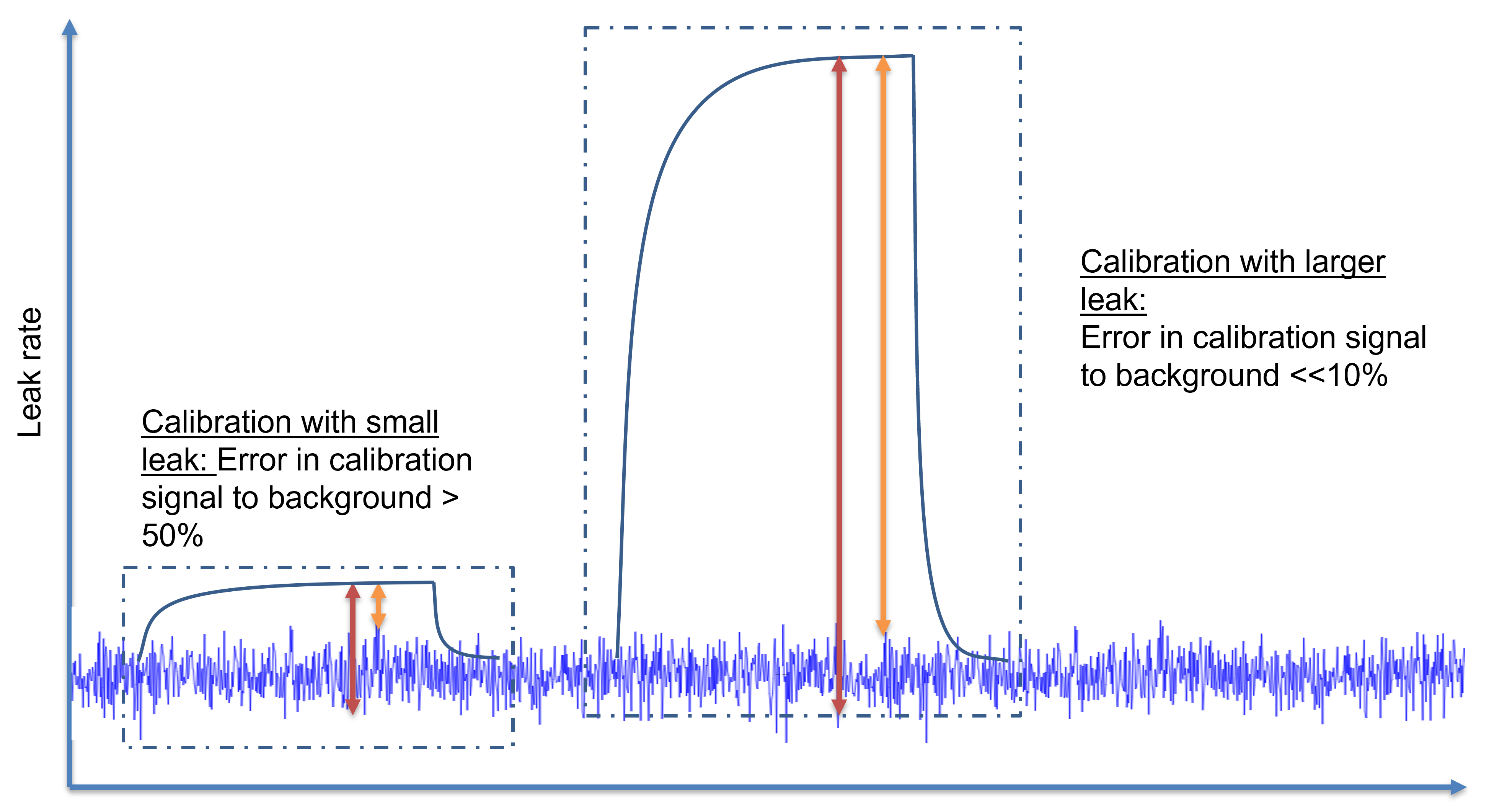
Using this safe calibration process requires leak detectors that show good linearity, so that a significantly smaller (or larger) leak rate will still be displayed accurately.
For verification of the leak testing system design, a second test leak may be used representing the reject leak rate to prove that the system can reliably find the desired leak size and has sufficient sensitivity.
Mistake 2: Using known leaky parts as verification leaks
Sometimes quality personnel is given the daily task to verify the proper functioning of a leak testing system. Using a part with a known leak can be a good approach, as this checks the complete leak testing system. However, just using leaky parts from production or even purposely creating leaky parts (e.g. by drilling holes) is not a reliable option. Parts from production may change their leak rate over time (e.g. due to dirt from production getting to the leak path and clogging it or due to temperature changes). Also, it is very difficult to find or create a production part with a leak rate close to the reject leak rate.
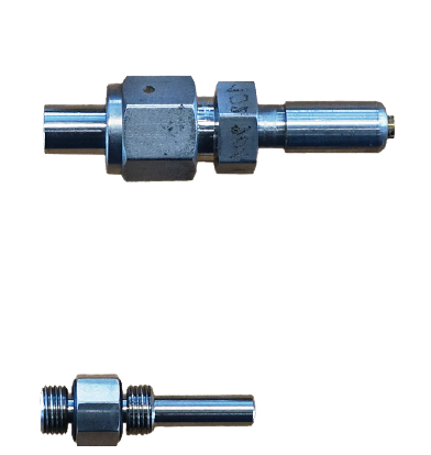
A good way around this problem is to use a production part with an open style leak installed that has a leak rate equivalent to the reject leak rate. Open style leaks are very repeatable and come with a test leak certificate traceable to national standards. Using this approach offers the ability to test the complete testing process, e.g. also including whether the tools used for filling with tracer gas create a proper sealing on the part.

Mistake 3: The calibration leak is installed in the wrong position of the leak testing system
Some vacuum leak testing systems have the test leak installed very close to the inlet of the leak detector or, use an internal calibration of the leak detector. Compared to a leak in the parts to be tested, this creates some differences in the leak size detected by the leak detector. The response time of the system (the time the helium takes to get to the sensor) may be longer for helium coming from the part compared to coming from the test leak close by. With a given measurement time, the signal from the part may not rise to its full level (while the signal from the test leak does), thus creating a too low leak rate value for the part being detected. Defective parts may still pass the test in that case! Or worse, the system may be designed to use large pumps and only part of the helium coming from the part in the chamber may be pumped to the leak detector (partial flow design) which will also lead to a significantly reduced helium signal from the part compared to the signal from the test leak.

The calibration leak should either be installed at the test chamber, or a master part with a certified test leak installed on the part may be used for calibration
Mistake 4: Ignoring the temperature dependance of a membrane test leak
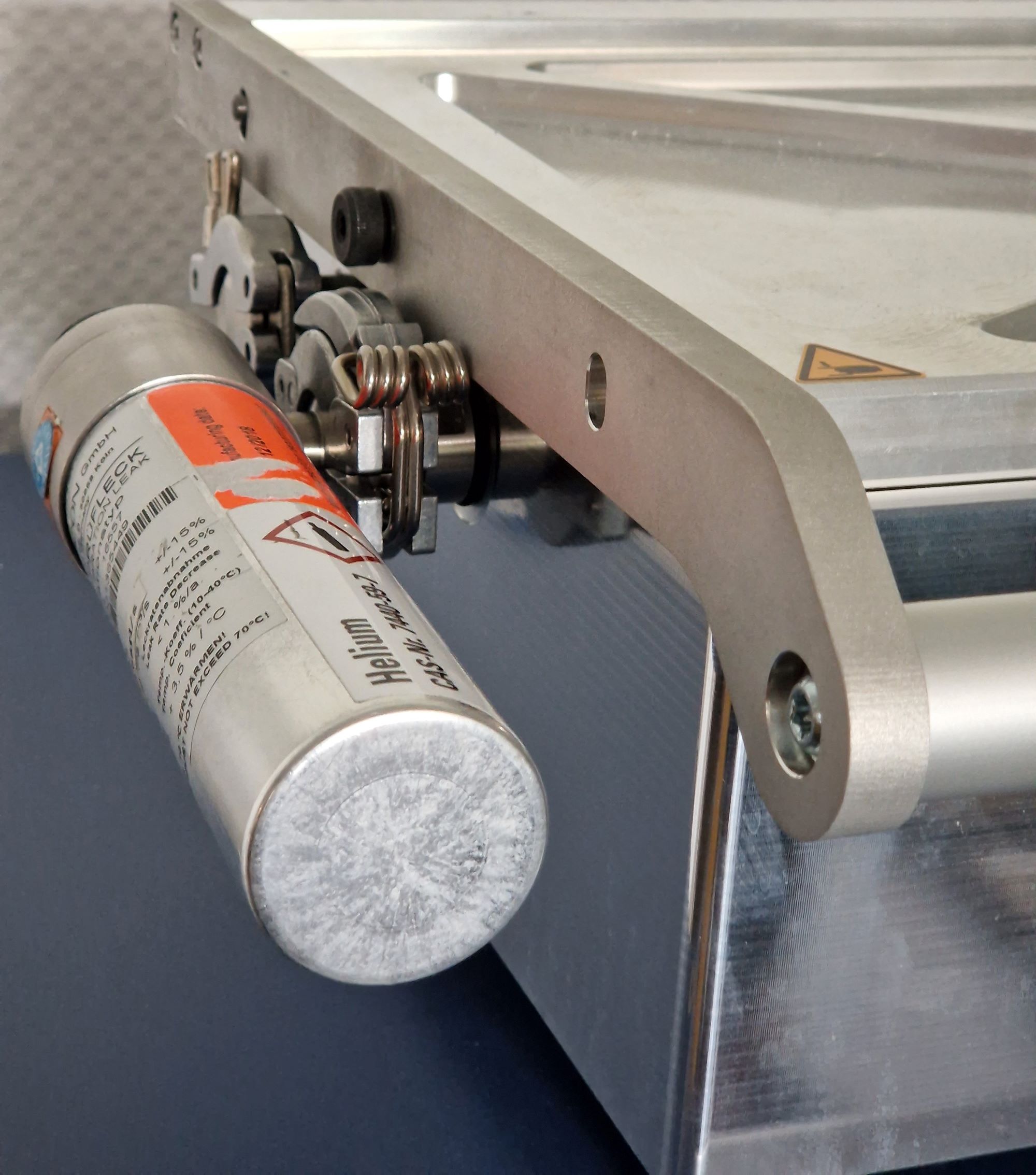
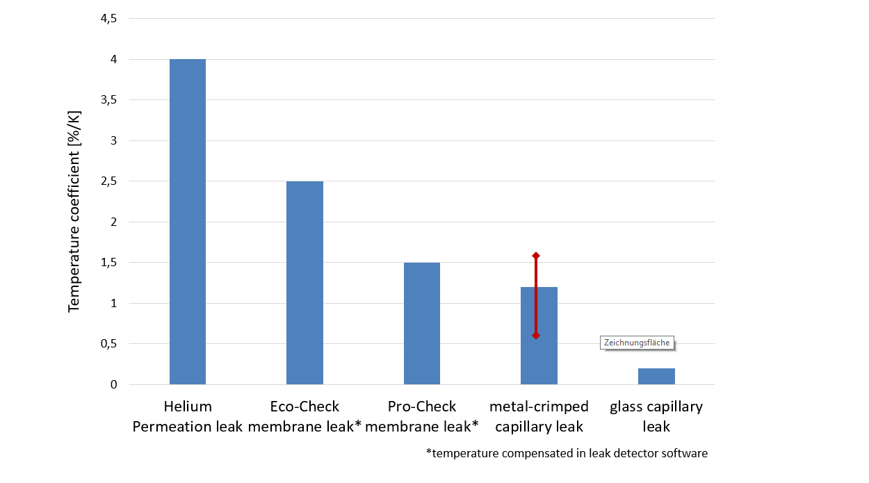
The leak rate of a test leak is basically a reduced flow of gas from a gas reservoir. There are two ways to reduce flow: by creating a very small opening (called diffusion or capillary leaks) or by controlling the flow through a membrane (called permeation or membrane leaks). Permeation through a membrane is highly temperature dependent, while the diffusion of gas is nearly temperature independent. Hence, capillary leaks can be used over a wider range of temperatures (within the temperature swings that may occur in a production area), while permeation leaks always need a correction factor for the temperature effect.
")
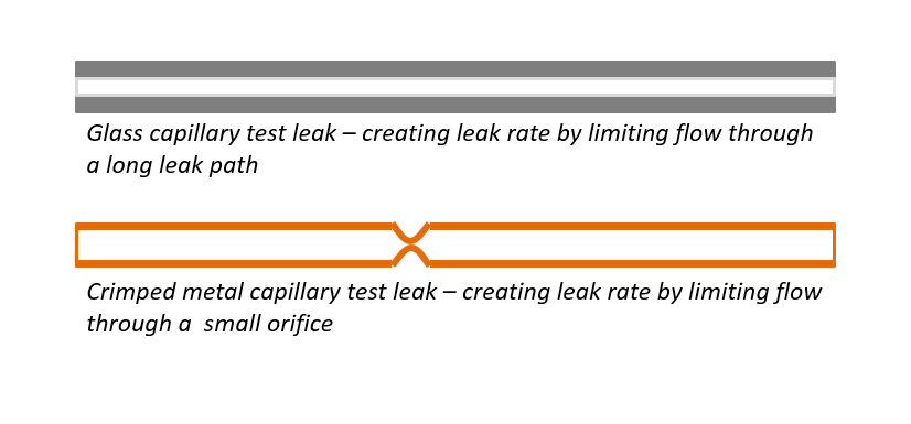
Mistake 5: Not all capillary leaks are the same
Capillary leaks may be made from either glass capillaries or metal capillaries. For the glass capillary leaks, the required leak rate is created by selecting a proper inner diameter of the capillary and adjusting the lengths of the capillary very accurately. In metal capillary leaks, the reduction of the flow is created by crimping the metal capillary to reduce the cross section and creating an orifice for flow reduction. For the same size leak, the smallest opening of the capillary is significantly larger in a glass capillary versus the crimped cross section of a metal capillary. Hence, metal capillary leaks are more prone to being blocked by small dust particles. Also metal capillary leaks are slightly more temperature dependent as metal expands with temperature more than glass and the small crimped cross section may change when the metal expands shrink.

Look at our on-demand webinar “Proper Leak Detection Calibration Processes for Highly Accurate Quality Control” and learn more.